Experimental testing on thermal test rigs makes it possible not only to validate the design and safety of a system on an industry-relevant scale, but also to avoid the cost of classic trial-and-error

The well-known desire to achieve a carbon neutral balance requires not only an increase in renewable generation, but also the development of thermal storage systems capable of managing this energy on demand.

However, thermal energy storage systems are a technology in continuous development, constantly searching for better efficiencies, lower maintenance or lower costs, among other things.

One way to shorten the development times of thermal storage systems and get them to market faster is through a thermal test rig or validation process capable of testing at a relevant scale in controlled facilities.

Prototyping and thermal testing facilities

Ensuring the design and safety of a thermal storage system operating under dynamic conditions at high temperatures calls for a prior validation process under controlled conditions.

This is generally performed in laboratory environments with equipment capable of reaching high temperatures and simulating operating conditions while the behavior of the system is recorded with very precise continuous monitoring mechanisms.

The Systems Engineering Group of CIC energiGUNE has three industrial hydraulic installations to cover a large number of thermal applications. These are three hydraulic loops designed to work with steam, thermal oil and air.


  • Air loop: This is an experimental hot air laboratory facility designed for testing materials and components for high temperature environments, such as different steels, complete thermal storage units, insulations...
  • Oil loop: This facility can operate with different thermal fluids as heat transfer fluid, for testing high temperature components and thermal storage systems for industrial processes and/or renewable energies.
  • Steam loop: This steam system test rig allows testing different materials and components for steam applications, under various temperature and pressure conditions, for industrial applications.


Facility

Operating temperatures

Flow rates

Pressure

Steam loop

100°C - 300°C

0 – 50 kg/h

40 bar

Oil loop

50°C - 400°C

0 - 25 m3/h

15 bar

Air loop

50°C - 800°C

0 - 360 kg/h

1 bar


These facilities are fully monitored in a controlled environment that allows to expose the test objects to variable flow rates and temperatures at an industry-relevant scale, obtaining accurate measurements of their behavior in real time and thus allowing to validate and optimize the design of the equipment under study.

These experimental tests avoid the cost derived from the classic "trial and error" and are based on a process composed of several systems:

  1. Pumping system: each installation has a variable speed electric pump or blower that can move the heat transfer fluids (air, oil and steam) within the specified flow rates.
  2. Heating system: this equipment generates the required heat using electrical resistances. The temperature control at the outlet of the system allows a fine regulation of the power of the system, fitting appropiately to the required test temperatures.
  3. Cooling system: they are made up of air/heat transfer fluid heat exchangers, which reduce the temperature of the fluid to be reinserted into the circuit under the conditions required for the tests.
  4. Control system: the loops are equipped with electronic processors that allow automatic and remote control of the installation, which is carried out in Labview® environment. In this way it is possible to program from different heating/cooling ramps, thermal cycles, up to changes in the direction of flow of the heat transfer fluid.
  5. Instrumentation: the installations are equipped with a set of properly calibrated digital instruments that allow complete monitoring of the installation. These devices include pressure and temperature sensors at different points of the installation and heat transfer fluid mass flow meters. These measurements, together with those required for the test object, are integrated into the control system for the correct operation of the tests.
  6. Thermography: the facility has a high quality FLIR A6752SC+ mobile infrared thermography equipment that captures the transient heat map of the test object. Subsequent post-processing allows any fine thermographic analysis to be performed on any area of the captured object.
  7. Testing object: there is an available surface up to 16 m2 to insert the equipment under study in the hydraulic loop, with a maximum height of 5 m. The facilities provide an easy and simple way to allow the conection of the testing object to the hydraulic loop.

Application areas of the thermal testing systems

Numerous industries benefit from this type of testing on the design and safety of high-temperature systems. Examples include the steel, foundry, automotive, chemical and ceramics industries, among others.

The following are some thermal test campaigns on industrial products that have provided relevant information for the design and optimization processes of these products:

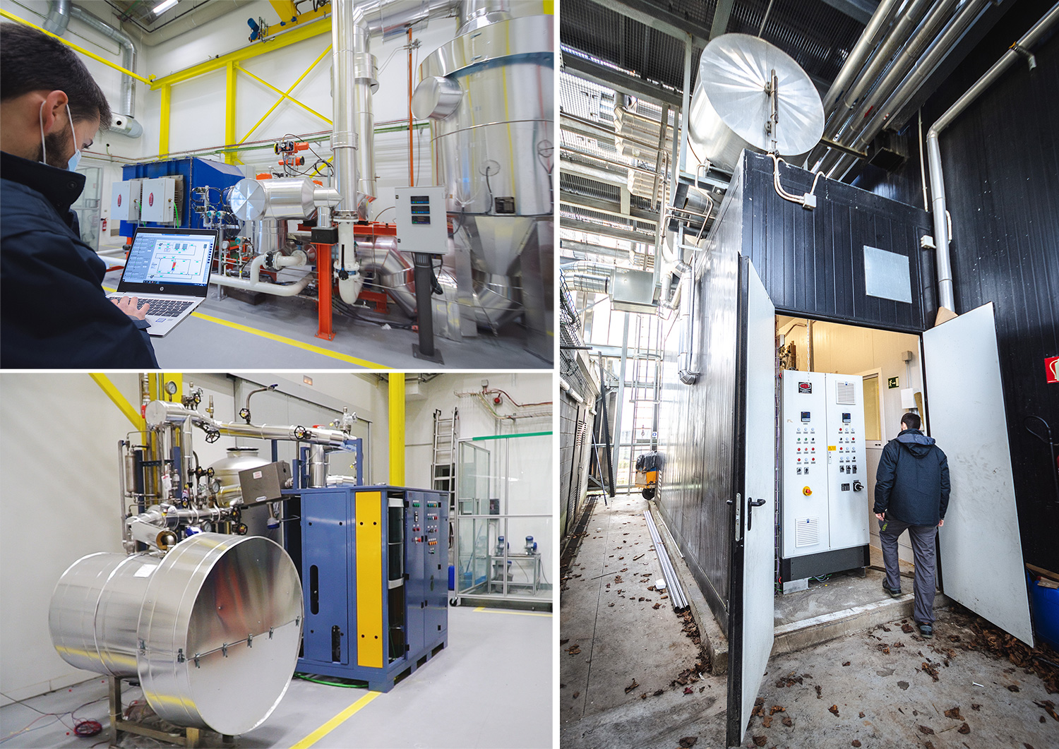
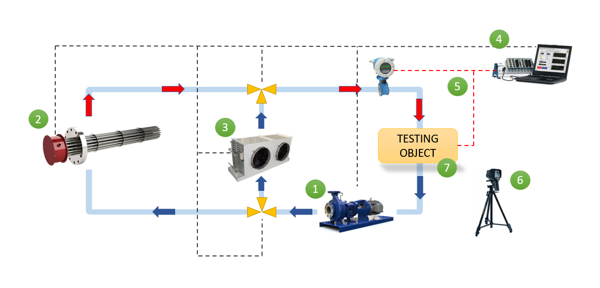
One of those case studies is the one carried out at the CIC energiGUNE facility with the oil loop. In this example, the facility was used to optimize and validate the design of a prototype of a thermal storage system for a solar thermal power plant using thermal oil with a temperature range between 180°C and 300°C. Accelerated life tests were carried out, determining not only the charging and discharging times of the storage, but also its behavior and mechanical deterioration. The results obtained made it possible to reduce the technological risk in the design of the commercial plant.

Regarding the air loop, as an example, the installation made it possible to compare the performance of two formulations of concrete for thermal heat storage, from 200°C to 600°C for industrial applications. To this end, two systems at a size close to real scale were exposed to thermal cycling, comparing their charging and discharging rates. The results made it possible to select the appropriate formulation within a very short time.

In another case, linked to the same air loop, it was used in conjunction with the thermography equipment to detect leaks in a plant supplying hot air at 700°C and showing flow rates way below the design points, which made it possible to optimize the plant´s operation.

Thanks to the steam loop, also, it was possible to validate a new steam accumulator design for cogeneration installations. For this purpose, the system was completely tested with steam at different pressure and flow levels, between 120°C and 300°C. As a result, both the operating ranges and the thermal capacities of the system were experimentally determined.

These examples demonstrate that the hydraulic loops offered by CIC energiGUNE are a way to obtain fast and reliable experimental results on products exposed to extreme thermal conditions. In this way, it is possible to drastically reduce product design times and achieve an early impact on turnover. In addition, the combination of these testing capabilities and the experience of our research team provides our partners with an additional way to introduce disruptive, efficient and low-cost advances in their designs.

Cookies on this website are used to personalize content and advertisements, provide social media features, and analyze traffic. You can get more information and configure your preferences HERE